
Overview
The 201-353-01 Connect Wall Mount Enclosure (Fault Monitored PSU) features a Fault Output relay, which can be used to signal when an issue occurs with the PSU. The output relay is normally closed, but will open in the event of a fault.
PSU faults reported by this output include:
-
Thermal shutdown due to overload.
-
Low-voltage PSU output fault.
-
Over-voltage PSU output fault.
-
12V output either shorted or overloaded.
-
Battery disconnected fault.
There are a number of potential ways to utilise this output, consequently what is presented here is one potential method to achieve monitoring of the PSU using the Nimbus Connect digital inputs.
In this example, Input 4 is utilised as Input 1 and 2 are commonly used for mode changes.
Wiring
Using suitable cable, run a pair of wires from the D1553 PSU Fault Output pins to the appropriate Input and a Common pins on the Nimbus Connect.
This example is using Input 4:
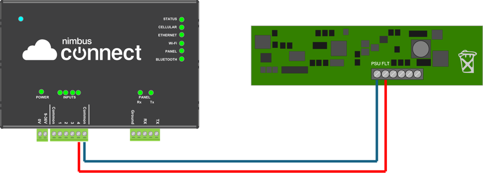
In normal operation the LED associated with the input will illuminate, due to the NORMALLY CLOSED operation of the relay.
Configuration
In Nimbus, edit the the Active Equipment and scroll down to the ‘Digital Inputs' field:
-
Configure Rising Edge action as “Fault Clear” and enter an appropriate user defined event description. This is the event reported when the PSU fault relay output goes from open to closed.
- Configure Falling Edge action as “Fault” and enter an appropriate user defined event description. This is the event reported when the PSU fault relay output goes from closed to open.

- Save changes.
Operation
In the event of one of the above PSU faults occurring, the PSU Fault Relay Output will open, and a FAULT event will be reported in Nimbus, with the associated ‘user defined event description’. When the fault is cleared, a FAULT CLEAR event will then be reported, with the appropriate description.
