
Overview
The event information output by the FC720 Event Printer is based on the 'Zone Customer Text Fields' (Device Description) provided in the Panel Configuration. The panel does NOT output any addressing information.
Consequently, it's essential that every Detection Zone has a unique Customer Text Field, and a copy of the panel configuration is imported into Nimbus as a ToC (see below), which will add addressing information required to support the operation of Servicing and Weekly Test recording.
This 'rule' is also true for Control Group Effects, which also require a unique Customer Text entry to show addressing information.
Important Note: The Addressing information reported by the FC720 is based on the physical loop address which is automatically addressed and will change when making changes to the loop wiring. Please enter the physical address into the Detection Zone description, this way you have control to ensure those addresses don't change. Nimbus will process address information from the Detection Zone description in the following formats:
-
LN:AAA or LN/AAA where N is the loop number and AAA is the device address
-
NA/B:AAA where N is the stub number, A/B is the stub (A or B) and AAA is the device address
Equipment required
From Nimbus
-
A Nimbus Connect or Fixed Gateway device
From the panel manufacturer/3rd party
-
3 core screened data cable
-
Siemens RS232 module (part no FCA2001-A1)
Panel configuration
Install the RS232 card in the panel, following the installation instructions provided by Siemens.
Ensure the RS232 card is configured as External printer, NOT Built-in printer.
Particular attention should be paid to section 13.5 detailing configuration of the Event Printer. If the RS232 card is not configured correctly, via the panel configuration software, then it will not output to Nimbus.
It is recommended that you change the External printer once setup so that it outputs less information, otherwise Nimbus will be flooded with information about every sounder activation.
Under Operation tab, expand External printer -> Visibility -> Site/Site.
Then on the Overview on the right you can de-select ALL event categories visible, then de-select Activations and Information categories.
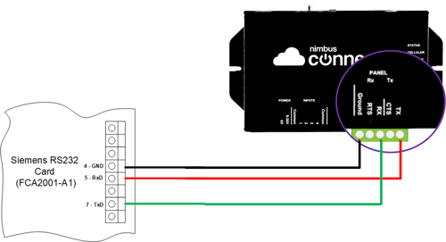
Wiring
Using 3 core screened data cable, wire as follows:
| RS232 Card | Nimbus RS232 |
| GND | Ground |
| RxD | Tx |
| TxD | Rx |
Troubleshooting
Do not select the option to Print the Event Memory, in order to output missed or historic events
If this option is selected, the Panel will stop outputting new events and instead begin outputting the contents of the buffer - a process that can take many minutes to complete.
Nimbus will ignore this output and not use the print out to update the Event Log. It will also wait until the output is complete. If the Panel is rebooted, potentially to stop the output, the Nimbus Connect MUST ALSO be rebooted to restore connectivity.
Loop numbers are wrong on ToC import
The Loop numbers are by default set by the Address of the C-NET card in the Hardware tree, to make the Loop number report how you want then name this C-NET card with the Loop number. EG Loop 1 or Loop 3, etc.
After importing a new ToC the servicing is wrong, some devices shown as tested when they are not and others show as untested but were tested
This could be because devices have been added to the loop since the ToC was originally imported, if these devices are mid loop the devices afterwards are automatically shifted to the next address. Please ensure the loop devices are named using the Address number to avoid this and safe address the device. Please read about this in the Overview section at the top of this page.